My experience with the air conditioner unit install was mostly positive. I researched the many brands/options and decided the best location would be the middle of the ceiling in the living room and lower on the wall in the back bedroom. Every building will be different so there is no way to give a rule of thumb. Most units I've seen are simply high on the wall and lead directly outside to the condenser, but I have a flat roof and short walls with wide windows that actually have no space for the higher wall unit. Those are around 34 inches long and I only had around 26 inches of wall space higher toward the ceiling. That's a problem because any higher wall installation would leave the inside unit hanging over the window.
Then I considered putting the copper lines through the roof behind the board and batten siding and then straight down through the original flat hot mopped asphalt into the ceiling. But, the ceiling units don't have line sets entering from the TOP, the line sets enter from one side. So I would have to cut a hole like two feet from the unit and bend the lines in a 90 degree so they would enter the ceiling and then connect to the unit. This ultimately seemed insane since it would mean cutting a hole in the absolute hottest part of the property, the roof/attic, in order to COOL my house. That makes no sense. I want to insulate the shit out of the attic, not cut a hole in it to let the hot air pour into my bedroom. Not to mention the high likelihood of a rain leak one day that would leak directly into the holes I cut into the asphalt attic cavity into my bedroom. Man, that made no sense.
 |
| The condenser didn't have to go here but the central location made sense since I had two zones on opposite ends of the house. It allowed one 16 ft line and another 25ft line, that could've been 16ft. So, two zones reached with two 16 ft lines is pretty good. The condenser split the distance between the two..and it was near the breaker box and there was already a cement pad there to mount it on. |
...So, I can't go in the ceiling, or the high wall. And that left only the lower wall...which seemed like the only problem is that I couldn't put a bed flush with the wall if I had an AC unit on the wall. But that was a problem I could deal with since I'm not sure a bed will ever go back there.
So, I estimated where the unit would hang and then realized the room is actually about 12 inches BELOW dirt grade, so if I put the unit flush with the floor the drain would have to go UP, which it can't do. So, in order to have the condensate drain flow down a little I had to hang the unit flush with the window sill. This looks like I hung it too high, but believe me the area below the unit is actually underground. Fortunately, I just missed having to mess with the electrical wires for that outlet to the right of the unit.

The ceiling unit was easier because when I demolished the insane 1/8'' plywood that was my ceiling, my plan was to hang the living room unit on the wall, which turned out to be solid stucco/adobe. So, the unit had to go in the middle of the joists...which gave me lots of flexibility once I had all the joists open. And fortunately the joists are very wide at 30'' on center instead of 14''. So, the unit fit easily.

So, placement is a big factor that most DIY videos do not appreciate. The manufacturer will provide a certain length of pre-flared copper refrigerant line. You can cut to customize the length, but I did not want to get into reflaring the copper lines, so I determined the exact location of the unit in order to accommodate the exact length of copper lines. This is a little backwards and definitely caused me some grief with the back room wall unit because I only drilled one hole and that hole had to leave exactly 18 inches INSIDE the wall, and then exactly 14'6'' OUTSIDE the wall that would terminate exactly at the spot where I planned to put the condenser unit on a cement platform. This simply complicated everything, and left me with about 4 inches of line that I had to bend in a slight U turn to shorten the termination location. The best way would be to simply buy a foot extra copper tubing and cut it to fit exactly where you put the condenser rather than loop or turn extra tubing to accommodate where you WANT to put the condenser. But if you don't want to flare the copper tubing then you have to get pretty creative with some lengths of string to approximate where the copper tubing will terminate. String didn't really work because it turns to sharp...copper wire would work better.
So, the first discussion one needs to have is about where you are placing the indoor units and if you want to flare the copper tubing or not. This discussion will end with a decision about what style of indoor unit it will be and where the hole will be drilled.
The installation of the indoor ceiling unit was made easy with a template Pioneer sent me. If I could hang the cardboard template then I could hang the 35 pound unit. They provided the threaded brackets too. and nuts. I did have to cut the bolts down because hanging it from the rafters put the unit too high on the bracket so the bolts actually hit the cover of the unit. I had to cut two inches off of them.
The wall unit had two L brackets that the unit hangs on. I screwed some wood to the wood frame the drywall is hung to and then screwed the L brackets to the wood, instead of to the drywall since it's not supported on the bottom. At first I thought I would build a little bench, but it's not heavy enough and the way I have it hanging on brackets that are screwed solidly into wood is secure as long as I don't get drunk and break into my own window and accidentally step on the unit getting into the room.
The whole indoor installation is just measuring wood and screwing things together. No big deal.
Terminating the control wires is pretty basic also. Just pick one of the control wire colors and go with that combination on the outside unit. Unit A RED/Blk/White....goes to 1/2/3 on the outside Unit A location....Red/Blk/white. You are just matching the combination with the unit location outside. I guess there is a primary and secondary location so I guess it would be possible to mess up and wire the control wires for Unit A into the outdoor unit B location, but connect the hoses for Unit A to Unit A. What would happen? Man, I guess it would get signals that don't correspond to the amount of cooling or heating it is controlling. I doubt the world would end, but your goal is just to match Unit A with the Unit A indoor unit and the indoor unit wires and line set in the same combination that you wired it to. A little more engineering would make this fool proof, but they kept the costs affordable by not getting wire harness engineering involved with connector clips that correspond to unit A and Unit B. It's probably better this way.
Now, the line sets are a little nerve-wracking to work with because they can be crimped and kinked and destroyed. You have to bend them in at least one 90 degree turn, and that could destroy the copper tubing if you are a little hasty. I felt good about every bend except one. I had to bend the line in a 90 and then bend it far back from the wall because of the grey conduit for my garage electrical wires. There was no other way to get the line set flush with the wall. And in the process of bending and then pulling and bending again in a difficult fashion I thought I felt the copper tubing bend a hair past the safe point. It bent a fraction of a degree a little too easily, which to my hands felt like I had kinked, not bent, the copper. That's the death of the tubing because it will obstruct the refrigerant. The best thing is to start fresh with new copper but I had gone so far that I kept going. I didn't even want to look at the kink because it meant so much more work and it was only a fraction of a hair. I felt all around the copper for signs of a kink or sharp edge but it still felt round so I decided to move on. Whatever, it's a rookie mistake but I was not careless or impatient and it's easy to bend those tubes a little too sharp and kink one.
So, barring any obvious kinking of the tubing, the next step is to connect the line set with the connections on the inside unit. This involves some insane math because I had to measure the flare diameter and when that didn't correspond to anything I used other information to determine I had a 1/4'' liquid line or 6.35mm and a 1/2 suction line...or 12.7mm and that corresponds to N.m of torque, which I then converted to Ft. Lb. It was a process easily done wrong and my math skills stopped with Ted Williams' batting average in 1941 so I'm not the best at this stuff, but I battled through it and came up with 11ft. lb of torque for the smaller line and 26ft lb for the larger line. But an adjustable torque wrench costs about $150 so I bought some crowfoot heads that fit on a click style 3/8'' head socket torque wrench and did the best I could do.
I will say that the process of getting exactly 11ft pound of torque on a connection that only has one moving side is not easy. One side of the connection is fixed because it is the flared end of another copper tube that is brazed in place to the evaporative coil. IT CAN NOT TURN. But you must exert 11 or 26 ft lb of torque on it no matter what you do. The only way to do this is to exert the exact amount of torque you are exerting in the opposite direction with the other wrench. This is a terrible design but I don't know enough about flared tubing to figure out a solution. No matter what you do, the side next to the coil can not turn. But you can't clamp it or put it in a vise. You simply have to exert the exact amount of torque on it that you are exerting with the other wrench so the torque cancels out, the fitting is torqued and tightened to 11 ft. lb, BUT ONLY ONE SIDE TURNED. Not easy. Oh, if you mess up and twist off the flare then you will have to replace the $600 unit because the coil will be destroyed.
 |
| Other folks just recommended getting two crescent wrenches and torquing them "GOOD AND TIGHT". Sure, are they going to come pay for the replacement if I mess it up. Hell, I even practiced on nuts and bolts to learn what 11 ft LB of torque "FELT" like before trying it on the copper. I was sweating for more than just the high temperature. |
 |
| This is an adapter for the 1/2'' line set and they included a crush washer so the brass fitting is crushing a brass washer that is basically a flare. I used leak stop gel on this also. |

 |
| That grey conduit really complicated things because the copper line set had to do a 90 degree into the house, and then another 90 degree UP to the unit connections, BUT it had to also hug the wall behind the grey electrical conduit at the same time. Man, that sucked. |
 |
| Some problems were my fault and some were the quality control fault at the wire harness factory. I don't know if Pioneer hired this part out, but fortunately I WORKED AT A WIRE HARNESS FACTORY, so I know exactly how this happened. The exterior insulation or sheath was cut during the final process of leaving me 5 inches of wire. The exterior insulation is very delicate so the tech basically cut too deep when they were stripping the outside insulation and they cut all four wires of the control wires. Now, it's obvious in this photo but at the time they made this mistake the black insulation was actually HIGHER, and probably covered up the cuts on the control wire. Only during travel and because I moved it a little did I expose the cuts on the control wires, which were bad enough that I could not leave it alone. I cut those wires off, then actually did the exact same mistake by cutting the black insulation too deep a few inches down. It's very delicate and in the factory I used to cut the outside insulation of a 4 wire combo WITH A RAZOR BLADE UNDER A MAGNIFYING GLASS. It was was the only way to go just deep enough to cut the black insulation but not the control wires and then examine the wires because at that point I could not simply cut the wires and start over because the wires had to be exactly 16 feet long, and not 15 feet, 5 inches. See? This was passed by a quality control supervisor because the tech probably pulled the wires up to cover the cuts. Or maybe they both blissfully missed the cut. My point is that they couldn't just cut off a few inches. They would have to drop this 16 ft wire down to 10 feet to match a different order since both ends have crimped on lugs. The lesson is to examine the wires first because a short across control wires might destroy the circuit board. |
 |
| The crush washer was a mystery at first but I later realized it belonged between the adapter and the fitting on the condenser. |
So, the critical parts of this installation are placing the indoor units, which will determine the kind of unit and the length of line. Then bending but not kinking the copper tubing. Then torquing, but not over torquing the flare fittings. Then examining the wiring for accuracy and integrity.
The last thing is commissioning the unit, which involves pressurizing with nitrogen, checking for leaks, and then vacuuming out the humidity and air with a vacuum pump screwed into the service valve.
Nitrogen test: If you are like me then you don't have a bottle of nitrogen laying around. And a study of the vacuum process reveals that there is a way to short cut the use of nitrogen. After the line set has been vacuumed completely of humidity and air then you can release ONLY 60 lb of refrigerant R410A. Now, that refrigerant is actually extra in the case of a 16 ft line so it's serving the same purpose of refrigerant, pressurizing the line so you can check for leaks.
I guess back in history there was a bleeder valve and a person would open the valve and then open the bleed valve and expel air until it became refrigerant and then close the bleed valve. This was a bit inefficient and also destroyed the ozone layer, so it's no longer practiced. But I thought if I vacuumed the line for 4 hours with my economy vacuum pump, then I could pressurize the line with a small fraction of refrigerant and then look for leaks and it would be like using nitrogen as long as I had really agonized over the torquing of the flare fittings.
So that is what I did. 4 hours of vacuuming down to Negative 30 Psi. FOUR HOURS running that pump for each line set. And when I had run the vacuum for 4 hours I then shut the valve to the manifold and waited not the "few minutes" the manual recommended, but I waited Hours and Hours. I waited hours because that vacuum should NEVER be lost in a system with no leaks. Right? Why should it ever go down if there are no leaks? Well, the manifold itself plus the connection to the service valve could easily leak. But I waited hours before deciding the vacuum was not moving and there was no humidity or air in the lines before releasing 60 psi of refrigerant and then scrutinizing all the flare fittings with soapy water, not once but for 30 minutes. I then increased the pressure to 120 psi and AGAIN scrutinized the flare fittings for leaks with soapy water. And again at 200 psi. And again when I maxed the dial out since the 16ft line is actually the minimum that is allowed with the pre-charged refrigerant, which accommodates between 16 and 25 feet. At 10 feet one must REMOVE refrigerant and at 30 feet, one must ADD refrigerant. Get it?
So, I scrutinized the flare fittings and the dial for hours because if a person takes shortcuts in one department then he better make up for in other departments.
The vacuum pump I bought was a
ZENY 3,5CFM Single-Stage 5
I consider this pump inadequate for any line set longer than 16 feet. Now, that might've changed had I used a nifty schrader valve remover tool, that removes the obstruction of the valve, but I didn't because I didn't see that one was available for less than $60. Removing that obstruction MIGHT've made the pump useful for the 25 foot line. But I will guess that it made no difference, that holding a vacuum on 50 feet of line (25 feet x 2) is not possible with a single stage 3CFM pump. That is my guess after my experience with this pump. I believe I did not reach negative 30 psi when I tried to vacuum the 25 feet of line. I came close to that, but I didn't reach the negative 30 psi. I DID reach negative 30 when I vacuumed the 16 ft line. Yes, I'm confident that line was purged of humidity and air after hours of pulling the vacuum. See, the fittings can all be leak-free. Yes, but that does not mean you vacuum has the sucking power to pull negative 30 psi. Nope. So, the 16 feet of line was short enough that it did pull and hold negative 30 psi. But the 25 foot line was too long and although it held any vacuum it reached, it did not ever reach negative 30, not even after 4 hours. It was always around 23 or maybe 25. If the gauge doesn't move after an hour at 25 then it is safe to say it's not going to move to 26 ever. Not after two days. It will always be 26. So, if I stop the pump and close the valve and it holds negative 26 psi for a few hours then that's where it is at. I can not say for sure what percentage of humidity and air I removed. MOST of the humidity and air? But that is not good enough. I realize the importance of this step but the tools I had were barely up to the task. My decision as part of the DIY ethic was to move forward in an imperfect world. One might say, "Oggy, just go buy the $400 vacuum pump and the schrader valve remover tool and do the job 'right'". But my answer is that there is no guarantee in this particular world that buying the better vacuum pump and valve remover tool WILL WORK BETTER. I realize the theory is that they will do the job better, but that's just speculation. They may not do any better than my cheap pump. It sucks but that is the world we live in. There is no guarantee the better tools will ever arrive at my house, and there is no guarantee they will work and there is no guarantee they will work better. All that is speculation. It would be interesting to experiment with $1000 worth of tools but I have more time than money so I can't experiment with anything. I have to get the job mostly done to the best of my ability with the tools I can afford in the time frame that I can deal with. I have more time than money. And there is no guarantee the more expensive tools will ever do the job better. I hate that it's the truth. I buy a $1200 van that goes to costa rica. Johnny Carson buys a $80k DeLorean and it breaks down the first day on the way to work. This is the world we live in. Now, salesmen will sell you the better tool on the theory it is worth the money, but that's a theory. I don't even want to own a $60 vacuum pump, let alone owning a $600 vacuum pump plus a schrader valve removal tool. DIY ethics is always a balance of cost effectiveness and experimentation and letting nature take its course. Take it one step further and add in my distrust of HVAC professionals. I don't even trust THEM to arrive on time with the right tools and the right skills. So, how would I ever trust myself to buy super expensive tools with alleged performance? No, I'm content in my time on earth to get buy with adequate tools for adequate equipment. The performance of this HVAC system is not life or death. I'm pretty close to throwing the whole thing, the house and everything, in the dumpster and driving back to Mexico, so it's not like this is some experiment that I'm invested in. Domestic living is insane. Talking about caulking and paint colors and different tile patters IS FUCKING INSANE. What kind of insanity is my life? I'm already disappointed that I had to really study the science of HVAC and building science. Like, there's a global pandemic RIGHT NOW, with media turning the hysteria dial up to 10 left and right, and I'm devoting my time to HVAC system study? Really? And I'm going to agonize over flare torque ratings? Are those numbers going to be on my gravestone? Probably not.
 |
| the stars aligned so the ceiling joist was in the way of the flare connections. I could've avoided cutting a chunk of the joist had I rotated the unit 90 degrees but that would've meant plumbing the drain 180 degrees which already felt complicated. I thought a 2x6'' joist could lose 1 inch of material. I didn't see an easy solution so I cut the part out that was in the way. The company did provide some pipe adapters for the drain hose but I've seen other installations using a compression fitting. |
 |
| The rear of the condenser unit with coil and cooling fins is totally unprotected from golfball sized hail that chips paint and breaks windows and destroys trees. I predict that the unit would last one year before some ricocheting hail destroyed the coil/cooling fins, so I built a high awning to provide plenty of air flow but deflect the hail. |
Here's an example of a recent hail storm that destroyed all the trees and vegetable plants in the neighborhood and would've destroyed the cooling fins on the back of any unprotected mini split system.
 |
| you can see this does not reach negative 30 psi. This is more like negative 24. Maybe the gauge is inaccurate and it is really negative 30 or maybe it is really negative 10. Who knows? A stronger pump would probably reach negative 30 psi. |
 |
| I was being optimistic when I thought that small hole would work. I ended up raising everything to get the drain hose to exit the wall above grade. |
 |
| The awning also protects the fairly cheap PVC line set cover that I don't expect to last very long due to sun damage. |
 |
| This is in the wall unit. 1/2/3 =Red/Blk/Wht. I wasn't impressed with how this was all arranged with zip ties actually connected to the copper coil and almost no way to avoid wires bumping into one another. |
 |
| Wiring in the cheap AC disconnect. The plastic panel just pulls out and I thought it had a screw so I destroyed the little plug. Then I had to create a rubber bushing to screw into. Bullshit. |
 |
| Adding a 240V double pole breaker. The hard part is picking the right breaker for your panel. They are not all interchangeable. Eaton goes with Eaton. Square D goes with Square D. You have to know what your panel is compatible with, not just the voltage and amperage you need. I only needed a 20A double pole breaker. |
 |
| wiring inside condenser. |
 |
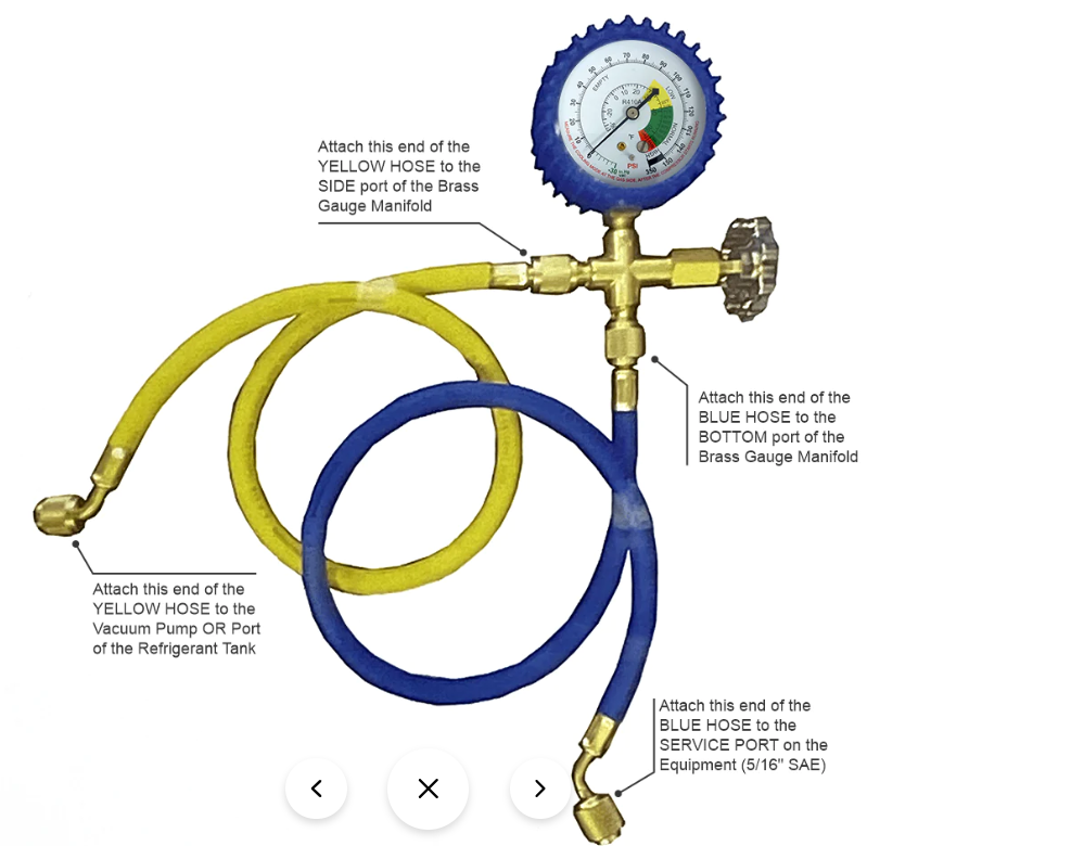
| THIS PHOTO SHOWS THE WRONG WAY TO HOOK THESE HOSES UP The yellow hose DOES go to the vacuum pump, and the blue hose DOES go to the condenser (although the colors really make no difference since they are identical hoses), but this particular gauge/manifold shuts off the port Opposite the knob so that port is the common one that should get the yellow hose attached. When I attached it like this I actually routed refrigerant THROUGH THE VACUUM PUMP. when I went to open the valve since there was suddenly no pressure reading. It was a bad surprise and could've blow up the hose if I didn't act quickly and close the service valve and bleed the refrigerant off. This is called learning the hard way and is odd because I had the hoses hooked up right originally but saw someone else hooking them up like this so I experimented and learned quickly that this manifold/gauge is not like all the others. |
 |
| From the manufacturer |
I juggle these topics all the time. Three Way light arrangements, Pergo tile, pandemics, sex drive, shoe size, calcium deposits under the skin, cancer. I've met some of the tradesmen in this area and I have no time for them. They seem incompetent, clueless, and expensive. I've decided I will do everything short of buying a backhoe. I'll dig like a miner. Fine. But I'm going to be realistic about my expectations. I aim for quality but I accept that what I reach will be adequate. And if it requires a revisiting then I will revisit it myself.
Basically, I would recommend a home owner installing the indoor units and the outdoor units and maybe getting the hoses lined up for connection but allowing aHVAC tech to make that connection with the high dollar torque wrench and leak stop. Then they can pressure test with nitrogen and vacuum the lines and release the refrigerant and check for operation. The proper tools basically would set you up to go into business commissioning mini split systems and run you $1000 while the HVAC tech might charge half that or less. I didn't get an estimate for a commissioning so I'm only guessing, but I'm pretty far from everything and it's summer and they are busy so I expect it would be extremely expensive to get an HVAC tech to do the work. Ultimately, I can't trust the local HVACs would do a better or even different job than myself. I've seen their work and I'm not impressed. Sure, an HVAC tech exists on Earth who can do the job right, but those ambitious types have long since fled this area of parched dirt leaving the dregs of the trade world behind to screw up every job they attend. Allegedly there is no warranty if I do the installation myself, but that makes no sense when I consider the licensed techs who would've been hired to do the job. There's no way they would've scrutinized each step like I did.
That's my conclusion and it affects my decisions about what I will attempt or not.
The two zone unit cost $2700, shipped and delivered and I ordered the fancy rubber feet for the condenser and the manifold and hose and the PVC line set cover. The pump was $60. The awning is just scrap but let's say $40. So, between $2800 and $3000 for a two zone mini split unit installed in two rooms with an awning. A simpler installation with a single wall unit can be only $800 so I definitely added quite a bit of money getting two zones with covers and feet and the items to vacuum the line. But I also think I pinched pennies, so $3500 DIY installation is not unreasonable. To pay a few guys to do the job would be thousands, perhaps $7000. A multi zone job could get an estimate for $10k. Each job and location would be different. Unfortunately, the heat in the desert, even at higher altitude, has reached intolerable levels. Houses that were built in the '50s with no need for HVAC, now are like ovens. Maybe people have become intolerant, and maybe it's a combination of the weather. I thought this area would be hot in the summer, but it's extremely hot and the house, despite being adobe, gets like an oven all night long. So, I had to do control the climate to live here.
UPDATE 9/2020: My system ran good all summer, every day for about two months of July and August. September was the arrival of cooler day temps. Then I got an email...The company I bought this system from responded to the vacuum pump dilemma a little late in my case. They figured out a way to use a disposable pressure canister to purge the line of air. without using a vacuum pump. It's more resource intensive, but the ultimate goal is probably reached without as many debates and micron gadgets. Each zone uses a pressure canister to purge the gas line...back to the open liquid line. Then you quickly connect the liquid end to the condenser and the line is purged. Then you pressurize it again to check for leaks. Thus, a vacuum pump is never used. I think this method is as reliable as the method I used with a crappy vacuum pump and no micron gauge and no core removal tool.
Either way, it's good the manufacturer understands the whole vacuum pump problem and is trying to solve it.

No comments:
Post a Comment